Getting Started with I2C: Hardware Connection
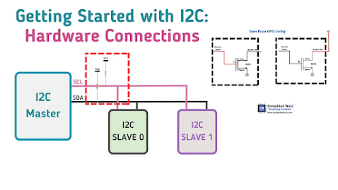
I2C (Inter Integrated Circuit) is a communication protocol used in embedded systems to connect microcontrollers and other integrated circuits. In order to guarantee dependable communication among devices in I2C, hardware components like resistors and capacitors perform a critical role.
The I2C protocol employs two signals — the data (SDA) and clock (SCL) lines — which are open-drain (or open-collector) pins. The pull-up resistors are required to maintain the high state of the data lines, and capacitors help to stabilize the voltage on the bus and filter out noise.
The formula for calculating the pull-up resistor value is
R = (Vcc — Voh) / Iol
and the formula for calculating the maximum allowable bus capacitance is
C = (Iol / (dV/dt)) * 1.2
Choosing appropriate values for resistors and capacitors is essential for reliable communication between devices.
Excessive capacitance or low resistance can cause signal degradation and errors in communication.
For more details, please refer the link shared below:
https://embeddedwala.com/Blogs/DigitalCommunication/Getting-Started-with-I2C:-Hardware-Connection

Comments
Post a Comment