Posts

Showing posts from March, 2023

Getting Started with SPI: A Beginner’s Guide

Image
  SPI (Serial Peripheral Interface)  is a  synchronous  communication protocol that enables data transfer between microcontrollers and peripheral devices. It is a  full-duplex , master-slave protocol which means data can be sent and received simultaneously. When the master device sends data to the slave device, the slave device can send data back to the master device without waiting for a separate read operation. It is commonly used in embedded systems, especially in applications requiring high-speed data transfer. The SPI protocol requires four pins: MOSI  (Master Output Slave Input): The MOSI pin is used by the master device to transmit data to the slave device. MISO  (Master Input Slave Output): The MISO pin is used by the slave device to transmit data back to the master device. SCLK  (Serial Clock): The SCLK pin provides the clock signal used to synchronize the data transfer between the master and slave devices. CS  (Slave Select): The CS pin is used by the master device to select

Getting Started with UART: A Beginner’s Guide

Image
  UART (Universal Asynchronous Receiver/Transmitter)  is a communication protocol commonly used in microcontrollers and other embedded systems. It allows for serial communication, enabling the transfer of data between two or more devices. Two main components in UART are:  a transmitter  and  a receiver . The transmitter converts parallel data from a microcontroller or computer into a serial stream of bits, while the receiver converts the serial stream of bits back into parallel data. The data is transmitted in the form of packets called frames, which consist of a start bit, data bits, optional parity bit, and stop bits. UART Packet Format As mentioned above, UART communication involves transmitting data in the form of  frames , with each frame consisting of a start bit, data bits, optional parity bit, and stop bit. Details of the frame is as below: The Start Bit : The start bit is a logic low (0) signal that indicates the beginning of the data frame. It is used to alert the receiver th

Getting Started with I2C: Code Example

Image
  In I2C communication , one device acts as the master and initiates the communication, while the other devices act as slaves and respond to the master’s commands. The master generates the clock signal and controls the data transfer, while the slaves respond to the commands sent by the master. Each device on the bus is identified by a unique 7-bit or 10-bit address, which is used by the master to address the slave device for data transfer. It also supports different data transfer formats such as byte mode, page mode, and sequential mode. The I2C protocol also includes error detection and correction mechanisms such as ACK/NACK signals and CRC checks to ensure reliable data transfer. In this post, Master-Slave code implementation is covered in detail. Image shared below is explaining the flow chart of the code. For each module explanation, please refer the link shared below: https://embeddedwala.com/Blogs/DigitalCommunication/Getting-Started-with-I2C:-Code-Example

Getting Started with I2C: What is Bus Arbitration

Image
  I2C (Inter-Integrated Circuit) is a widely used communication protocol for embedded systems. It enables communication between different components using a synchronous serial communication mechanism. One of its key features is arbitration, which resolves conflicts that occur when two or more devices try to transmit data at the same time. Arbitration in I2C is based on a wired-AND logic system, where devices on the bus can pull the bus lines low but not high. If two or more devices try to transmit data simultaneously, the device that pulls the bus lines low first wins the arbitration and can transmit its data. The other device backs off and waits for the next opportunity to transmit its data. For example, if two I2C Master devices are connected to the same bus and both attempt to transmit data to the same I2C Slave , an arbitration process will occur to determine which device has priority. The device that pulls the SDA line low first will win the arbitration and proceed to transmit i

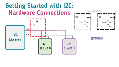
Getting Started with I2C: Hardware Connection

Image
  I2C (Inter Integrated Circuit) is a communication protocol used in embedded systems to connect microcontrollers and other integrated circuits. In order to guarantee dependable communication among devices in I2C, hardware components like resistors and capacitors perform a critical role. The I2C protocol employs two signals — the data ( SDA ) and clock ( SCL ) lines — which are open-drain (or open-collector) pins. The pull-up resistors are required to maintain the high state of the data lines, and capacitors help to stabilize the voltage on the bus and filter out noise. The formula for calculating the pull-up resistor value is R = (Vcc — Voh) / Iol and the formula for calculating the maximum allowable bus capacitance is C = (Iol / (dV/dt)) * 1.2 Choosing appropriate values for resistors and capacitors is essential for reliable communication between devices. Excessive capacitance or low resistance can cause signal degradation and errors in communication. For more details, please refer

Getting Started with I2C: What is Clock Stretching?

Image
In  I2C(Inter-Integrated Circuit)   communication , the   master  device initiates the communication by sending a   start condition   and then sending the   slave device’s address . The slave device then responds with an   ACK   (acknowledge) signal to indicate that it has received the address correctly. If the slave device needs more time to process the data, it can hold the clock signal low to pause the communication temporarily. This is known as   clock stretching . Clock stretching is a technique used in communication protocols to allow slower devices to slow down the clock signal of a faster device. This technique is commonly used in I2C communication, where the clock stretching is performed by the slave device. This is useful in scenarios where multiple devices of different speeds are connected to the same bus. However, clock stretching can also cause  timing issues  if not implemented correctly. If the slave device holds the clock signal low for too long, the master device may i

Getting Started with I2C: A Beginner’s Guide

Image
    Getting Started with I2C I2C (Inter-Integrated Circuit) is a two-wire interface developed by Philips Semiconductors in the 1980s to connect low-speed devices such as sensors and microcontrollers. It uses a master-slave architecture, where the master controls communication between devices. The protocol uses only two signal lines, SDA (Serial Data) and SCL (Serial Clock), and a synchronous clock to synchronize communication between the devices. I2C communication is half-duplex , and pull-up resistors are required on both the SDA and SCL lines. I2C supports two addressing modes: 7-bit addressing and 10-bit addressing. In 7-bit addressing, each device is assigned a unique 7-bit address. In 10-bit addressing, each device is assigned a unique 10-bit address, and it is used when a large number of devices need to be connected to the I2C bus. I2C communication starts with a start condition, which is a high to low transition on the SDA line while the SCL line is high. After the start condit